Vectric Tutorial: How to Create a 3D Terrain Map
Get busy this summer with another cool CNC project! This time, learn how to create a 3D Terrain Map using VCarve Pro and Desktop.
This 3D terrain map tutorial will outline all the important steps during the process including the basics when working with terrain satellite images. Think file types, sources, and more! A detailed step-by-step process is also accessible on SpindleTV for your reference.
What is a 3D Terrain Map?

Before anything else, a 3D terrain map visualizes the height and shape of terrains in three dimensions. It can come as a digital image or 3D model and it’s mostly used for environmental management, urban planning, military operations, and so on.
Aesthetic-wise, a 3D terrain map is a cool indoor decoration or gift too! You can create mini 3D models to give as a gift to a hiker friend or create your own ‘travel corner’ at home where you show off models of places you’ve traveled to before.
Perfect for crafters looking for a unique CNC project to get busy over during the weekend!
How to Create a 3D Terrain Map
1. Find a 3D Terrain Map ImagE
3D terrain map images are harder to find than regular photos because they’re not captured in a ‘normal’ way. Rather than cameras or cellphones, they’re created using complex techniques like aerial photogrammetry, satellite imaging, and Light Detection and Ranging (LiDAR).
That’s why satellite images also come in various file formats which will matter later as we go through the process of creating a CNC 3D Terrain Map.
OBJ and STL - The most recommended 3D model file that is compatible with Vectric software
DEM - larger satellite-type files that need to be converted to be used on Vectric software. The data is very taxing as well for regular computers.
Greyscale images - height map images—not just black and white images! Can be used with Vectric Aspire only.
Geotiff

https://touchterrain.geol.iastate.edu/ is one of the specialized websites where you can find 3D terrain map images for free. It covers almost every corner of the world and all you have to do is type down the place you’re looking for!
It also allows you to control how you see the satellite image. So as seen in the bottom left corner, you have options to adjust the height, the zoom, and the puzzle or how detailed you want the image to appear.
Save your chosen image and it should come into your computer as an OBJ file!
2. Import File
After choosing an image you can start with the Job Setup. Since we’re working on a square image, we’ll use a 12x12-inch large and a 1.5-inch thick as the base. Feel free to work with your usual job setup!

Then, click Import a Component or 3D Model under 3D Modelling tools to transfer the image to your base. It will take a few seconds longer considering the size of the file and as soon as it’s uploaded, you’ll need to size it down and set the Initial Orientation to Front to fix the image.

Want to start a CNC wood carving business from home?
Download our 18-page guide packed with tips and advice from successful customers who have already made it happen.
Take the first step towards turning your passion into a profitable business!
Connect with Digital Wood Carver

3.Create a 3D Roughing Toolpath

If you’re working with a terrain image with a lot of deep valleys and crannies, then you’ll want to start by creating a Roughing Toolpath.
It’s best to use a smaller end mill for this project, preferably a ¼ inch end mill. However, this will take much longer than usual and may not be suitable for those with not much time on their hands. In that case, you can pick larger end mills as long as you’re fine with not having perfect carves on smaller crannies!
Since your image occupies the entire space of your material, tick Machining Boundary as the Machining Limit for the project. Set the Machining Allowance to 0.04, the Roughing Strategy to Z level, and Raster X to cut along the X-axis.
Remember: You’ll need to look for alternative clamping methods for this project since the machine will cut through the entire material. You can use hot glue, double-sided carpet tape, etc.

Name your toolpath, calculate, and preview to check for any needed changes.
4.Create the Finishing Toolpath
Finally, create a toolpath for your finishing cut. Set the tool to a ⅛ inch tapered ball nose end mill to carve through the tiniest details of the terrain. If your image is even more detailed than this one, you can also drop down to a smaller-sized end mill to get the best quality!
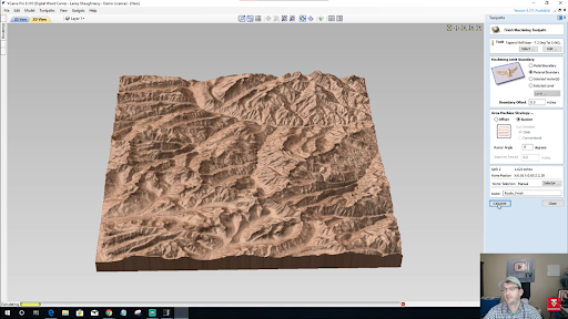
Lastly, set the Material Boundary as the Machining limit and tick Raster as the machining strategy. Name your toolpath, calculate, and preview!
On VCarve Pro and Desktop, you can also try to enhance your model by playing around with the Component Properties. Here, you can adjust the Shape Height to emphasize the details or add a zero plane to patch up any holes that may show up on the bottom of your model.

And that sums it up! Hopefully, this guide has given you a better idea on how the whole design process works and how to use Vectric Aspire.
For a full step-by-step walkthrough on how to create a 3D terrain map on CNC, check out Laney’s LIVE Vectric Tutorial on How to Create 3D Terrain Maps where he explores other terrain types as well!
Don’t forget to like and Subscribe to the SpindleTV channel to keep up with the latest updates and to join our LIVE Vectric classes every other week.