A Look at 3 Approaches to Text-on-Text Designs
Want to explore Text-on-Text designs? Take a look at these three approaches you can use to get a great result!
For this guide, we’ll be introducing you to three different ways to design a text-on-text project. That includes:
The Triple Layer Approach
The Four Layer Approach
The Modeled Stacked Text Approach (exclusive for Vectric Aspire Software)
For a detailed run of every process, watch Laney’s LIVE tutorial video on SpindleTV.
Triple Layer Approach
1. Create Your Layers.
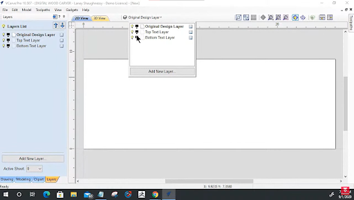
Right off the bat when you’re happy with your job setup, we are going to start by organizing your layers. From the top of the view bar, you can see a drop down list where you can access and manage your layers.
You’ll be needing three layers for this approach so you’ll have to rename your current layer and add two more.
Here are the layers you’ll need:
Original Layer
Top Text Layer
Bottom Layer
Make sure that your Original Design Layer is active. You’ll know it is when its name is in bold. Also, since we’ll be working on the original design layer first, we’ll need to turn off the other two layers for now.
After that, let’s create our project border using the Draw Rectangle Tool. We just drag over the entire project area, and we offset it inwards. Type in how thick you want your border to be on the Distance box and click Offset.
2. Add Text
Next, add in your text.
For a text-on-text project, it’s best to start with the text at the back before adding in the text that you want to have in front. In this case, we’ll have SpindleTV at the back, Laney Shaughnessey in front, and a quick tagline at the bottom.

Want to start a CNC wood carving business from home?

Download our 18-page guide packed with tips and advice from successful customers who have already made it happen.
Take the first step towards turning your passion into a profitable business!
Choose your preferred font and make sure to keep it balanced on your board using the Alignment tools.

For the tagline on the bottom, we want the protruding rather than the carved effect. So, we’ll create a rectangle boundary around it, and offset it outwards to ⅛ of an inch so that it doesn’t get carved away.
3. Separate the Layers
Now that your design is ready, you can now copy each element into their designated layer.
For the Bottom Layer, select the text at the further back, the border and the tagline. Right click and Copy to Layer – Bottom Layer.For the Top Text Layer, select the front text and the border and do the same except copy it to the Front Text Layer.
After separating the vectors, you can work on each layer separately by turning off the other layers.
Top Text Layer
When using script typefaces, you might encounter overlapping lines in your text. You’re going to have to clean up those extra vectors since we don’t want the machine to run through the same area twice.
Bottom Text Layer
Offset the bottom text inward based on the VBit that you will use. This is how deep you want your machine to cut through your material. You can check out how Laney finds the exact measurement using the Measure Tool in the tutorial.

In this case, we’ll offset it by 0.0722. Make sure that you delete the original and don’t worry if it looks too skinny, it’ll look exactly like how it was earlier when it’s carved.
Finally, reselect your back text and group it together so the software treats it as one vector.
Connect with Digital Wood Carver
4.Weld the Back and Front Text

When you’re done with the back text, you can now go back to the front text and copy it onto the Back Text Layer and convert it into curves. This way, it’s much easier to weld the texts together.
Select the two texts and weld the two together using the Weld Tool. Turn on the Front Text Layer, and now you’re set to run the toolpath.
5.Run the Toolpath
Starting with the Top Text Layer, set the Start Depth to 0, Flat Depth to ⅛ inch, 60 degree VBit, and a Flat Area Clarence Tool of ¼ and ⅛ inch End Mill. Tick Raster Cut, and calculate.

For the Bottom Text Layer, select the border, the welded text and the inner border of the tagline.
Then, we create a VCarve Toolpath with the same tools as the Top Text except we’ll have a Flat Depth of ¼ inch.
Calculate toolpath to preview.

Onto our last toolpath, select the tagline and outer boundary of the tagline.
Then, set the Start Depth and Flat Depth to ⅛ inch, use an End Mill of ⅛ inch as well, tick Raster cut, and calculate.

Always look out for any overlapping lines or unprotected vectors. Don’t be afraid to make adjustments!
Four Layer Approach
Another way you can go about Text-on-Text Design is the Four Layer Approach. As the name implies, it has four layers:
Original Layer
Top Text Layer
Bottom Text Layer
Welded Text Layer
The first few steps for this approach are similar to the Triple Layer Approach:
Create the border
Add the Text
You should have two sets – the first text is for the bottom layer, and the other for the top layer.

After adding the text on the Original Layer, you can now copy each one to their designated layer. Top text plus the border for the Top Text Layer, and ONLY the back text (no border!) for the Bottom Text Layer.
1.Working on the Top and Bottom Text Layers
Turn off the Original Layer, activate the Top Text Layer, and determine your desired text height and VBit. In our case, we’ll be going for a 1/8 inch pocket depth, a 60 degree VBit, and a 0.058 offset for both the top and bottom text.
If your text happens to be a script font, make sure to clean up overlapping lines. You could use the Scissor Tool for this, but the quickest would be to weld the text together.

After welding, copy the welded Top Text and paste it onto the Welded Layer.
For the bottom text, all you need to do is activate the bottom text layer, group the vectors together and copy it onto the Welded Text Layer.
2. Working on the Welded Layer
Offset the welded text copied earlier outward by 0.058 and make sure to delete the original vector. Then, group the offset vectors together. There should be no sharp corners and the original border should be deleted.

Then, offset the border inward by the same magic number, 0.058, and delete the original vector. This will make the text look a lot thicker, but it gets better. Just trust the process!
Select the welded top and bottom text and weld the two groups together.
3.Creating the Toolpath

The toolpathing will be a bit different for this approach.
Starting with the Top Text Layer, let’s set the Start Depth to 0, Flat Depth to 0.1, and End Mills to ⅛ inch and ¼ inch. Rename the Toolpath created and Calculate.
Now, let’s hop onto the Welded Text Layer. For this Toolpath, everything stays the same except for the Start Depth which will now become 0.1 which was where the previous Toolpath left off. This way, you can carve just as deep as you initially wanted.
Rename the Toolpath, calculate, and preview.
Modeled Stacked Text Approach
For those who use the Vectric Aspire Software, another approach you could do is the Modeled Text Approach. Preliminaries are exactly the same as the previous approaches—setup the project, create your border, and add in the text. However, you’ll notice some changes later in the process!
For that reason, we’re repeating the same design as the Triple Layer Approach.
Pro Tip: Always use Very High or Extremely High modeling resolution for your projects for the best results.
Firstly, let’s get the text back to its original places and typeface. Make sure they’re centered and when ready, we can jump straight into the good part–Modeling.
1. Modeling the Components

For easier viewing, go to a 2D Split View and let’s start with modeling the Bottom Text. In this stage, you have the freedom to play with your model however you want. So don’t feel obliged to follow every number on this tutorial—this is just a guide after all!

Select the Bottom Text and open the Create Shape tool under the Modeling menu. For the bottom text, we’re looking to create a curved profile at a 90 degree curve, with a base height of ⅛ of an inch.
Tick Limit to Height of 1/16 of an inch for a rounded edge, rename the component, and click Apply. This should automatically reflect on the bottom half of your screen!
Now let’s create a new component for the top text. We do the exact same process here, except we want the top text to be a bit higher than the bottom text. So, we’ll set the Limit to Height to ⅛ of an inch instead and we should have it merged onto the bottom text. When done, rename the component and click Apply.

And lastly, we create another component for the tagline, set the base height to ⅛ inch, limit to 1/32 inch and add it to other components. Rename, and click apply!
2. Add a Draft
When done, you’ll notice that the walls of the texts are far too sharp and straightened–which we don’t want. Thus, we’ll add an angle around it to soften the sides and make it more appealing.
To do so, drag over the three components to select them and Add Draft. You can manually drag to find the best angle. For us, we’re going at a 22 degree angle.

Adding a draft will create a new component that combines all three layers, so now you can turn off the visibility of the other layers and create an out vector boundary around it.
When you’re satisfied, click Apply and you’re ready to create a toolpath!
3.Creating a Toolpath
One thing you have to remember when creating a toolpath for this approach is the height of your material which you can find on your Material Setup. Note this down as this will serve as the basis for how deep you want your machine to cut through.
Clearing Toolpath

Select your border and the outermost boundary you created for your text and click Pocket Toolpath. Set the cut depth to the height of your material, or in this case 0.2813, combine a ¼ and ⅛ inch end mills, and tick Raster cut. Then, you can rename the toolpath, calculate, and preview.
Roughing Toolpath

Now let’s select the 3D Roughing Toolpath and tick Model Boundary. Sticking on the ¼ inch End Mill, we want the boundary offset to be at ⅛ inch. We’ll also want to set a Machining Allowance of 0.4 and a Z Level Raster, this way, your vectors blend in nicely.
Rename the toolpath, calculate, and preview. It might not look like much right now but having a rough cut makes a huge difference.
Finishing Toolpath

To finish up, let’s jump into the Finish Machining Toolpath and use a 1/16 inch Tapered Ball Nose. Set the Machining limit to Model Boundary at an offset of ⅛ inch and Raster. Rename the toolpath and calculate.
And that’s a wrap! Make sure to save both your design and toolpaths so you won’t have to repeat the process every time you do a similar project. To follow through the entire step-by-step process with Laney, just visit the full tutorial on SpindleTV.
Don’t forget to like and Subscribe to the SpindleTV channel to keep up with the latest updates and to join our LIVE Vectric classes every other week.